Essay
Information Security Specialist Diploma. Part No. 2 - Stationary SmartLight device
A short preface Hello, Habr! This article is the second in the “Diploma of an Information Security Specialist” series, in which I talk about my experience in writing a final qualifying thesis for...
A short preface
Hello, Habr!
This article is the second in the series “Diploma of an Information Security Specialist,” in which I talk about my experience in writing a final qualifying thesis for the higher education program “Computer Security.” B previous article I described a mathematical model and the formation of a methodology for ensuring the security of Internet of Things devices using Bluetooth Low Energy technology as a communication protocol.
In this article we will talk about the creation of one of the Internet of Things devices - a stationary SmartLight device, the development of which was carried out without implementing any of the protection mechanisms I proposed in the first part. If you have not had time to read the first part of the series of articles, I advise you to read it first in order to better understand the context of what is happening.
Technological part
B first part In the series of articles “Diploma of an Information Security Specialist”, I already told you that I managed to break my thesis into 3 parts:
-
Research part ( BLE , IoT )
-
Design part (mathematical model, protection mechanisms, security techniques)
-
Technological part (stationary device, portable device, mobile application, NSD )
Since in the previous part we looked at the formation of the methodology and the mathematical model, we can move on to the technological part.
In fact, this is the most practical side of my research. In order to test the resulting methodology (and demonstrate its effectiveness within the framework of the work), I decided that there was a need to assemble several Internet of Things devices myself. Firstly, I will be able to work directly with hardware (and I just love it). Secondly, I will be able to clearly demonstrate the process of implementing the protection mechanisms from my methodology at the device development stage. And thirdly, I will be able to demonstrate everything live to the commission during the defense VKR (which I eventually did).
Also, I would be able to use these devices in the future to practice practical skills in the direction of defense and attack (not so long ago I acquired the well-known Flipper Zero, but have not yet had time to try using it to attack my devices, although this is in the plans).
Internet of Things devices
Development of Internet of Things devices using the DALL-E neural network
I decided that I would make two IoT devices: a stationary device without implementing security mechanisms and a portable device with the implementation of these mechanisms.
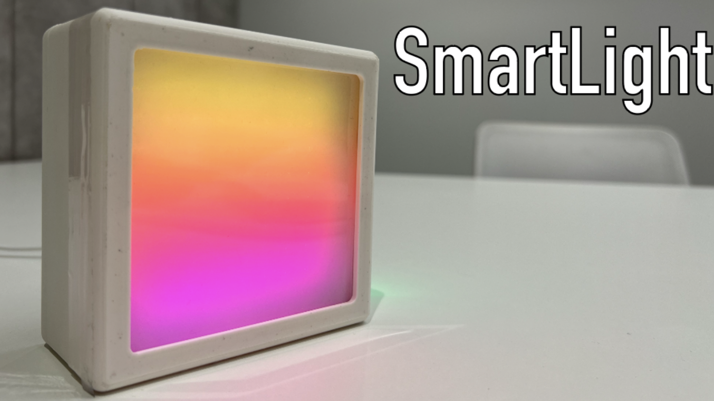
My creativity was enough for a smart lamp IR and smart heart rate monitor. In order not to torment myself for a long time with choosing suitable names for these devices, I decided to call them SmartLight (lamp) and SmartPulse (heart rate monitor).
In this article I will tell you about the development of SmartLight, and in the next one about SmartPulse. I will attach a demonstration of the functionality of both devices in an article dedicated to writing a mobile application for interacting with them via a smartphone (and without resorting to applications like nRF Connect), since I am not eager to duplicate the same material in different articles.
Stationary SmartLight device
When I already clearly understood and accepted the fact that I would be developing a lamp and a heart rate monitor, I realized that I absolutely did not want to just make a device that could glow and nothing more. With the heart rate monitor, things were a little simpler, since I planned (and eventually implemented) protection mechanisms in it, which already made it at least a little more interesting than without them. What interesting things could be implemented within the framework of a “smart” (relatively smart) device whose purpose is to shine?
I wanted to try to expand its potential functionality a little, so as not to stop at the LED matrix connected to the microcontroller. At that moment, I decided to look for what was interesting in my box with sensors, boards and wires. And I found the electrochromic film that I ordered a year ago. In terms of its size, it fit perfectly into my ideas about the future lamp. I also found a light sensor, which I used a long time ago in various projects back in my school days. So, gradually thinking, I came to the concept of SmartLight.
Luminaire concept with electrochromic film
Conceptually, I imagined a small device that could be placed, for example, on your desk or near your bed. The device had to operate in two modes: automatic and manual.
In automatic mode, the lamp itself determines when to turn on the light element, depending on the level of illumination of the space surrounding it. How useful this function is in an apartment is debatable, but I needed to go with this device to defend my thesis, and not to a crowdfunding site, so I decided that I wanted to bring this to life. I also thought about implementing the ability to adjust the brightness of the light element depending on the light level, which is possible through PWM , but at that time we were pressed for time, so we had to cut some functional features, including this one.
In manual mode, the user independently controls the lamp using a mobile application (which was only in plans at that time). I didn't want to implement just turning the light element on and off. It's basic, but it's boring. Therefore, to this functionality I added the ability to control electrochromic film, which could scatter and focus the light of the matrix, as well as several additional features Features: turning on the glow effect of the light element and sending a text message to it in the form of a creeping line. There’s no particular point to it, I just wanted to do it, and no one tried to stop me.
The bottom line is this:
-
The device must be small in sizeso that it can be placed next to a working or sleeping place (I have no idea where else a stationary lamp could be useful)
-
The device must be stationary , that is, work from the network, since I wanted to show various kinds of devices, and in my plans a heart rate monitor was supposed to be portable
-
The device must operate in two modes : automatic and manual
-
In automatic mode:
-
Information about light levels is collected
-
The light element turns on and off depending on the light level
-
-
In manual mode:
-
The user turns the light element on and off using a mobile application
-
The user turns on and off the electrochromic film using a mobile application
-
The user switches the glow effects of the device's light element using a mobile application
-
The user sends a text message to the light element of the device in the form of a creeping line using a mobile application, and the script for turning on the electrochromic film is automatically triggered (otherwise the message would not be visible)
-
-
-
Wireless data transmission technology - BLE
Having decided on the functionality of the device, I moved on to searching for all the necessary components to implement the hardware of the future lamp.
Hardware
In order to understand what exactly is needed to implement all the functions of the device, I compared the class of an electronic component with a functional part. The result is the following:
|
Electronic component |
Device functionality |
|---|---|
|
Microcontroller |
Device control, data transfer using BLE technology |
|
LED matrix |
Implementation of the functionality of the light element |
|
Light level sensor |
Determining the illumination level for further turning on/off the light element of the device in automatic control mode |
|
Electrochromic film |
Scattering and focusing the light emitted by a light element |
|
Voltage converter |
Converting DC to AC with increasing voltage to ensure the functionality of the electrochromic film |
|
AA batteries |
Additional power supply for electrochromic film |
|
Electromechanical relay |
Control of turning on and off the electrochromic film at increased voltage |
|
LEDs |
Indication of connection/disconnection via BLE and switching of device control modes |
As can be seen from the table, some components are necessary exclusively for the correct operation of the electrochromic film (aka PDLC Film). Let me explain this point in a little more detail.
Electrochromic film
Electrochromic film or PDLC Film is essentially a layer of liquid crystals located between two conductive films coated with an insulating layer on the outside. We will omit a detailed definition of PDLC and a description of the technology; there is plenty of this on the Internet. To make life easier for everyone who is curious, I will attachlink, where you can read more about this.
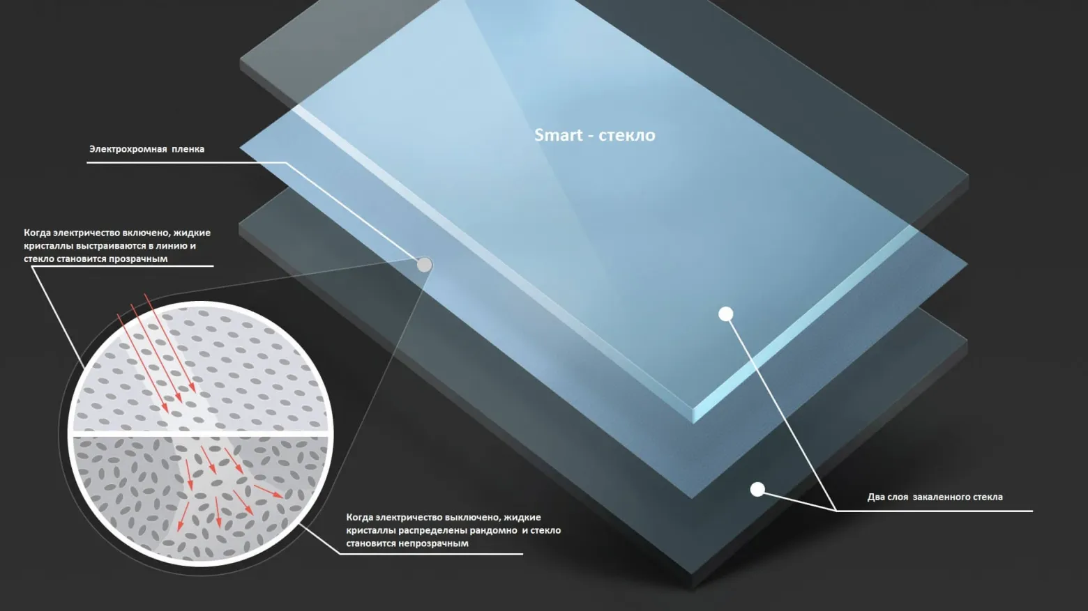
Smart glass device based on electrochromic film
The fact is that the electrochromic film that was at my disposal operated exclusively on alternating current with a voltage of 65 Volts. This was indicated in its technical characteristics, and was checked by me personally (because we do it first and then read the instructions). In this case, power supply from the network would be impossible due to the fact that the voltage required to operate the electrochromic film would kill the microcontroller if its power cable was used for these purposes. I admit that it was possible to come up with something much smarter and power the microcontroller and electrochromic film through one socket, but I did not have enough time, knowledge, or experience for this (I would be grateful if someone gives me an idea on how to implement this and not burn the microcontroller). Therefore, I decided to use additional power in my circuit.
Here, 2 AA batteries (popularly called AA batteries) helped me a lot. The only problem was that they only provided 3 Volts DC, which is a little short of 65 Volts AC. But the problem was solved the moment I was able to find a boost DC/AC converter that did the job perfectly. The multimeter showed me the required values, which I was incredibly happy about.
A single-channel electromechanical relay (I didn’t have another) was necessary in the circuit for connecting the electrochromic film to the microcontroller in order to, in principle, realize the ability to control this film using a board. There is nothing new here, everything is exactly the same as if you needed to connect a light bulb to the Arduino.
Let's move on to the light element, or more precisely to the LED matrix that implements its functionality.
LED matrix
I chose an LED matrix as a light element, since it is quite bright, thin (easier to place in the case) and at the same time makes it possible to control each individual LED in a targeted manner, which was necessary to implement glow effects and visualize the user’s text message in the form of a creeping line. In general, it is advisable to supply additional power to such matrices to ensure adequate performance, but I ended up connecting it directly to the power pin of the microcontroller (which, by the way, causes minor problems in its operation, so be smart and take such nuances into account when designing the circuit/board/device).
LEDs
To indicate switching device operating modes (automatic and manual), as well as to display the device connection status (whether the device is connected to the smartphone via BLE or not), I used regular RGB LEDs. Since there is nothing more to add about the display, let’s move on to the “sweet” part, which I decided to leave for last. To the microcontroller.
Microcontroller
After analyzing the market and realizing that I wouldn’t have enough time to figure it out with STM, I decided to use ESP32 as one of the most proven options for this kind of project. I chose the NodeMCU-32 development board based on the ESP-WROOM-32 chip running a 32-bit Tensilica Xtensa LX6 processor. At the moment this technology is outdated, but is still actively used.
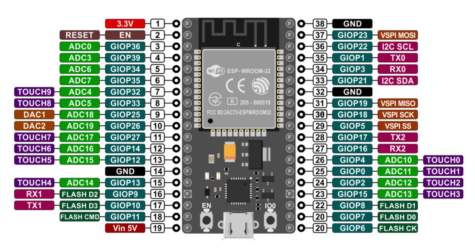
NodeMCU-32 pinout
I don’t see the point in talking much about the NodeMCU-32 itself, as well as about the ESP32, and as in the case of electrochromic film, I’ll leave it link for those interested.
My version of ESP32 supports the BLE 4.0 specification, which is now quite outdated, but nevertheless there are a large number of different devices on the market that use this version of Bluetooth Low Energy. In the framework of the thesis, this is rather an advantage, since the main task of SmartLight is to depict a theoretically valid IoT device without security mechanisms, and the popularity of BLE 4.0 makes it possible to get closer to the most plausible version of what can actually be purchased in the mass market.
Component connection diagram
After all the necessary electronic components for the future device were selected, I developed a diagram for connecting them to the microcontroller board.
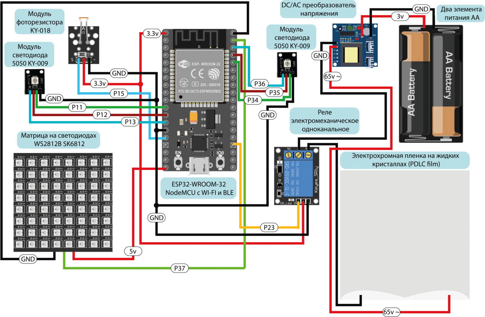
Electronic components connection diagram
Unfortunately, the stage with the implementation of this circuit on a breadboard will have to be omitted, because I forgot to capture this moment, and it is not interesting to talk in detail about how I connected the components to the board on a breadboard.
Software part
Although I decided not to focus on the stage when the circuit in the picture was transformed into an assembled system on a breadboard, one cannot help but say that it was at that moment that I started writing the firmware. I wrote certain code fragments for controlling individual components even before this, but all the code was assembled only at the stage with a ready-made device layout on the board, since this was the most optimal and effective option for testing and debugging the SmartLight software part.
Development environment and programming language
For me, the issue of choosing a programming language and development environment was decided before I had identified all the necessary electronic components. I decided to use the Arduino IDE with its version of the C++ language. In a situation where deadlines are quite tight, there is no need to move to a lower level (which cannot be said about SmartPulse, but more on that in the next article), and everything that was conceived in terms of functionality can be easily implemented on a conditional Arduino Uno (except for working with BLE, since Uno can’t do this “out of the box” without additional modules), there is no point in complicating your life and using something other than this development environment for a similar new microcontrollers (IMHO). I understand that in the case of the ESP32, such an environment is ESP-IDF, and not Arduino IDE, but in my opinion, many things are much easier to implement in C++ than in C, when it comes to the device functionality mentioned in this article.
I will not describe the process of connecting the NodeMCU-32 through the board manager in the development environment and loading the firmware onto the device, so as not to bloat the article, but I will leave it for those interested linkon the guide. Let's move straight to code analysis.
Firmware
In this article, I don’t see the point of completely posting the entire firmware. If interested, its full version can be seen in the attachments to VKR , as well as on GitHub . I would also like to apologize in advance to those who may be offended by my code. I didn’t have time to finalize it and bring it to fruition, since in addition to two devices, I also had to write a mobile application, run the NSD and correctly describe everything in my thesis. Therefore, if suddenly a powerful specialist came across my article, who implements OOP in assembler as a hobby, then I sincerely ask you to be more lenient towards my work.
All code can be divided into conditional logical (structural blocks).
|
Structural block |
Purpose and functionality |
|---|---|
|
Connecting libraries |
Import libraries for BLE and LED matrix control. |
|
Definition of Constants and Variables |
Initializing device parameters, including pins and global variables, defining objects to control the LED matrix. |
|
Functionality of the LED matrix |
Functions for displaying text and creating visual effects. |
|
BLE functionality |
Setting up a BLE server, creating services and characteristics, BLE event handlers. |
|
Light sensor integration |
Reading and processing data from the light sensor for automatic operation of the device. |
|
Electrochromic Film Control |
Functions for monitoring electrochromic film. |
|
Device Boot Welcome Script |
Implementation of a welcome script when turning on the device. |
|
Main loop |
Continuous execution of device functions. |
In this article, I will only tell you about the most interesting functions, because I’m not sure that anyone will be very interested in reading about connecting libraries or outputting data from a photoresistor.
In order to immediately show the main “features” of SmartLight during the thesis defense, I decided to write a greeting script that fires after turning on the device (I registered it in void setup). In it, I turned on the electrochromic film so that the contents of the greeting text could be seen in the form of a creeping line on the LED matrix.
matrix.begin();
matrix.setTextWrap(false);
matrix.setBrightness(10);
matrix.setTextColor(colors[0]);
String HelloMsg = utf8rus("Hello! My name is SmartLight. Maxim brought me together. Glad to shine for you!");

for (int i = 0; i <= matrix.width() + 6 * HelloMsg.length(); i++) {
  matrix.fillScreen(10);
  matrix.setCursor(x, 0);
  matrix.print(HelloMsg);
  if(--x < -410) {
    x = matrix.width();
  } matrix.show();
  delay(80);
}
digitalWrite(PIN_RELAY, LOW);
After the greeting ends, the electrochromic film turns off, and the device itself continues to operate in automatic mode.
The fourth code block of the SmartLight fixed device configures and manages BLE, allowing the device to communicate with external BLE devices such as smartphones or other smart devices. This block contains definitions of classes and methods responsible for operating the BLE server and processing BLE events. Since the code uses several services and characteristics, we will analyze the general BLE logic as an example, because in all cases it will be the same. Let's look at the example of transmitting data on the light level via BLE.
To begin with, let’s designate the characteristic that will contain the value of the illumination level from the photoresistor.
BLECharacteristic* pLevelLightCharacteristic; // Pointer to BLE characteristic for light level
Next, you need to create a BLE server and set a name for the device (it will be displayed when searching for devices available for connection).BLEDevice::createServercreates a server instance to handle incoming connections and communications.
BLEServer* pServer; // Pointer to BLE server
BLEDevice::init("SmartLight"); // Initialize a BLE device named "SmartLight"
pServer = BLEDevice::createServer(); // Create a BLE server to process connections and events
pServer->setCallbacks(new MyServerCallbacks()); // Set up callbacks for the server to handle server events
And set a callback class for it.
// Class for processing BLE server events
class MyServerCallbacks : public BLEServerCallbacks {
  void onConnect(BLEServer* pServer) { // Function called when the device connects to the BLE server
    deviceConnected = true; // Set a flag indicating that the device is connected
  };
  void onDisconnect(BLEServer* pServer) { // Function called when the device is disconnected from the BLE server
    deviceConnected = false; // Reset the flag indicating that the device is connected
  }
};
Next, specialized services and characteristics are created for the server, each of which has a uniqueUUIDand certain properties.
BLEService* pLevelLightService = pServer->createService(BLEUUID((uint16_t)0x170D)); // Create a Bluetooth service with the specified UUID (0x170D) - light level service
pLevelLightCharacteristic = pLevelLightService->createCharacteristic(BLEUUID((uint16_t)0x2A31), BLECharacteristic::PROPERTY_READ | BLECharacteristic::PROPERTY_NOTIFY); // Create a characteristic for a service with the specified UUID (0x2A31) and set its READ and NOTIFY properties
BLEDescriptor* pDescriptor = new BLEDescriptor(BLEUUID((uint16_t)0x2902)); // Create a handle for the characteristic with the specified UUID (0x2902)
pLevelLightCharacteristic->addDescriptor(pDescriptor); // Add a descriptor to the characteristic
For greater clarity, I will outline the schematic structure of a BLE package, where a device profile consists of many services, consisting of many characteristics, in which three parameters are designated: properties, value and descriptor.
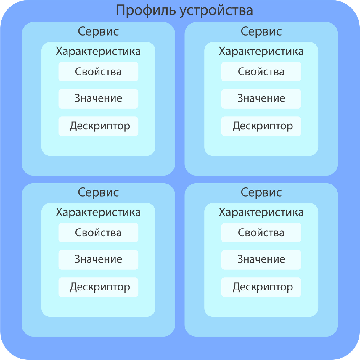
BLE packet structure diagram
Only three properties are defined:
-
PROPERTY_READ (read property value)
-
PROPERTY_WRITE (writing a value to a property)
-
PROPERTY_NOTIFY (subscription to notifications about value changes, in which we can receive a new property value every time it changes)
As you can see from the previous code snippet, for the characteristic
pLevelLightCharacteristic
properties used
PROPERTY_NOTIFY
and
PROPERTY_READ
, since the illumination level data will not be static.
Next, let's start the service
pLevelLightService->start(); // Start the light level service
After starting the service, you need to configure the server to send characteristic packages
pLevelLightService
and set mailing parameters.
BLEDevice::startAdvertising()
starts sending packets so that you can connect to the device and read the data of these packets
BLEAdvertising* pAdvertising = pServer->getAdvertising(); // Receiving an Advertising object from the BLE server
pAdvertising->addServiceUUID(pLevelLightService->getUUID()); // Adding UUIDs (unique identifiers) for the light level service
pAdvertising->setScanResponse(false); // Setting the Scan Response parameter to false - disabling the scanning response
pAdvertising->setMinPreferred(0x06); // Set the minimum preferred scan interval
pAdvertising->setMinPreferred(0x12); // Set the maximum preferred scan interval
BLEDevice::startAdvertising(); // Visibility to other devices
Next, we implement a condition under which we transfer data on the light level from the sensor to the characteristic value if a connection to the device has been detected. This code fragment also shows the implementation of changing the color of the LED indicator for connecting to SmartLight via BLE.
if (deviceConnected) { // Check if any device is connected via BLE
  pLevelLightCharacteristic->setValue(lightValue); // Set the value of the characteristic with illumination
  pLevelLightCharacteristic->notify(); // Transmitting data on security level in the form of a notification
  digitalWrite(LED1_2, 255); // Switch the connection LED to green
  digitalWrite(LED1_3, 0);
} else { // If the device is not connected
  digitalWrite(LED1_2, 0);
  digitalWrite(LED1_3, 255); // Connection LED glows blue
  BLEDevice::startAdvertising(); // Visibility to other devices
  }
As I mentioned earlier in this article, I decided to implement a feature to display a custom message on the light element of the device in the form of a ticker. Since the message will be transmitted using a mobile application on the user’s smartphone, this process also uses BLE. In order for this to be possible, in one of the characteristics,
responsible for transmitting a message, it is necessary to implement the property of writing a value in it. If this property is implemented in the same way as for reading, which we have already discussed, then to enable the desired mode on the LED matrix, you must use an event handler. Its function is taken over by the callback class
RunLineCharacteristicCallbacks
.
// Class for processing writing to the BLE characteristic responsible for the "creeping line"
class RunLineCharacteristicCallbacks : public BLECharacteristicCallbacks {
  void onWrite(BLECharacteristic* pCharacteristic) { // Function called when writing a value to a characteristic
    std::string value = pCharacteristic->getValue(); // Getting the value written to the characteristic
    if (value.length() > 0) { // Check the length of the received value
      Msg = value.c_str(); // Convert the resulting value to a string and store it in the Msg variable
      showType = 4; // Set the animation type to "creeping line"
      startShow(showType); // Start animation
      showType = 2; //Turn off the matrix
      startShow(showType); //Start mode
    } else { // If the value was not written (empty string)
        showType = 2; //Turn off the matrix
        startShow(showType); //Start mode
      }
  }
};
Device prototype
After I assembled the device on a breadboard and wrote the firmware, I wanted to see what it could actually look like in a physical package. What caught my eye was a cardboard box with a transparent element on the top side, which was the right size for the entire hardware.
Without thinking twice, I decided to try to put all the hardware into it.
SmartLight out of the box
The result was satisfactory, but I didn’t want to settle on a mock-up of the device in a cardboard box. I wanted to move away from DIY and improvised materials to something more thoughtful and logical. At that moment I realized that I wanted to see my device in a plastic case.
Case development
To begin with, I made a freehand sketch of everything I would like to see in the housing, including the LED matrix support elements and rough calculations of all sizes. Naturally, there was no precision in the calculations and lines. I just needed to visualize my ideas about the appearance of the device.
SmartLight body sketch
I decided to make the case collapsible in order to simplify the process of assembling the device in it. It consists of three parts:
-
Front cover (in this part of the body there is a square hole for placing an electrochromic film and implementing the main function of the lamp - to shine)
-
Frame (placement of the LED matrix, light sensor, indicators and device power cable)
-
Back cover (fixing the microcontroller, relay, batteries, converter)
Unfortunately, there was no time to think through the case better. For example, it would be nice to have a hole on the back cover for replacing batteries without opening the device, as well as normal board latches. But I decided to leave everything as is, h so as not to ruin yourself on printing in the future (small parts are difficult to print properly, so the cost of the case could be higher than it was in the end).
As you can see from the sketch, there are protrusions in the central part of the body (frame). They are needed to accommodate the LED matrix, which is a necessity, since if the light element is placed too close to the electrochromic film (or even glued to it), then the diffusion effect will not be achieved, because each individual LED will be visible through the film. At the stage of installing the components in the box, one could also see that the LED matrix is located at a certain distance from the electrochromic film.
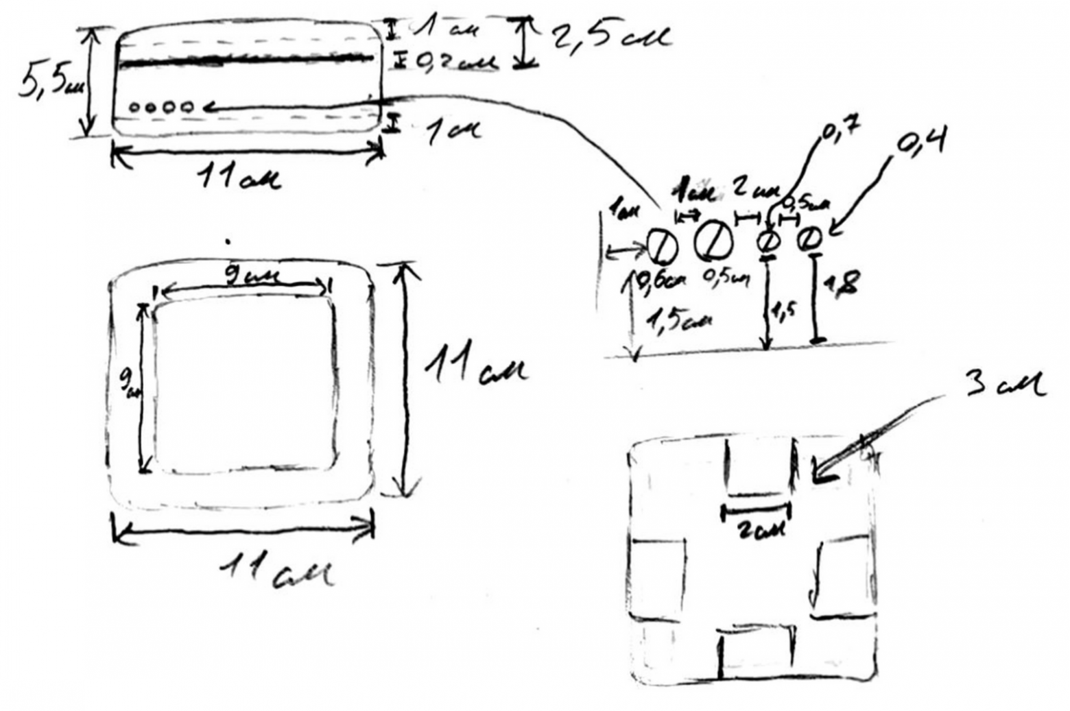
When I finally understood what exactly the case would look like outside and inside, I needed to clearly define all the scales by which I could create a 3D model of the case for further printing. I wanted to see drawings of all parts of the hull.
My girlfriend, Anya, helped me a lot in this process ( @ShabrovaAS ), who offered her help and, in fact, did absolutely most of the work herself at the design stage and preparation of the final version of the drawings.
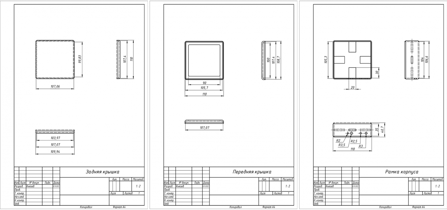
Drawings of SmartLight housing components
Based on these drawings, models of each of the three parts of the body were prepared in Autodesk Inventor for their further printing on a 3D printer. The original hull models are also available in the project's public repository at GitHub .
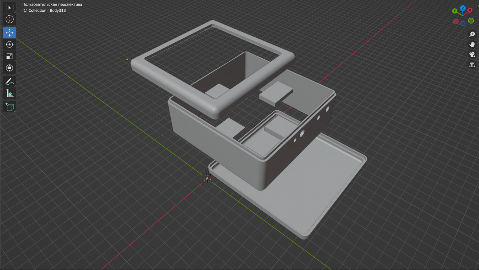
3D model of the case disassembled
After preparing the models, I printed them in the laboratory. When choosing between PLA plastic and ABS for printing, I chose the latter because it is more suitable for housings of various devices.
The printing result can be seen in the photographs. Unfortunately, I don’t have my own 3D printer, although I plan to purchase one in the future (I would be grateful if knowledgeable people in the comments would recommend good and affordable options for home use).
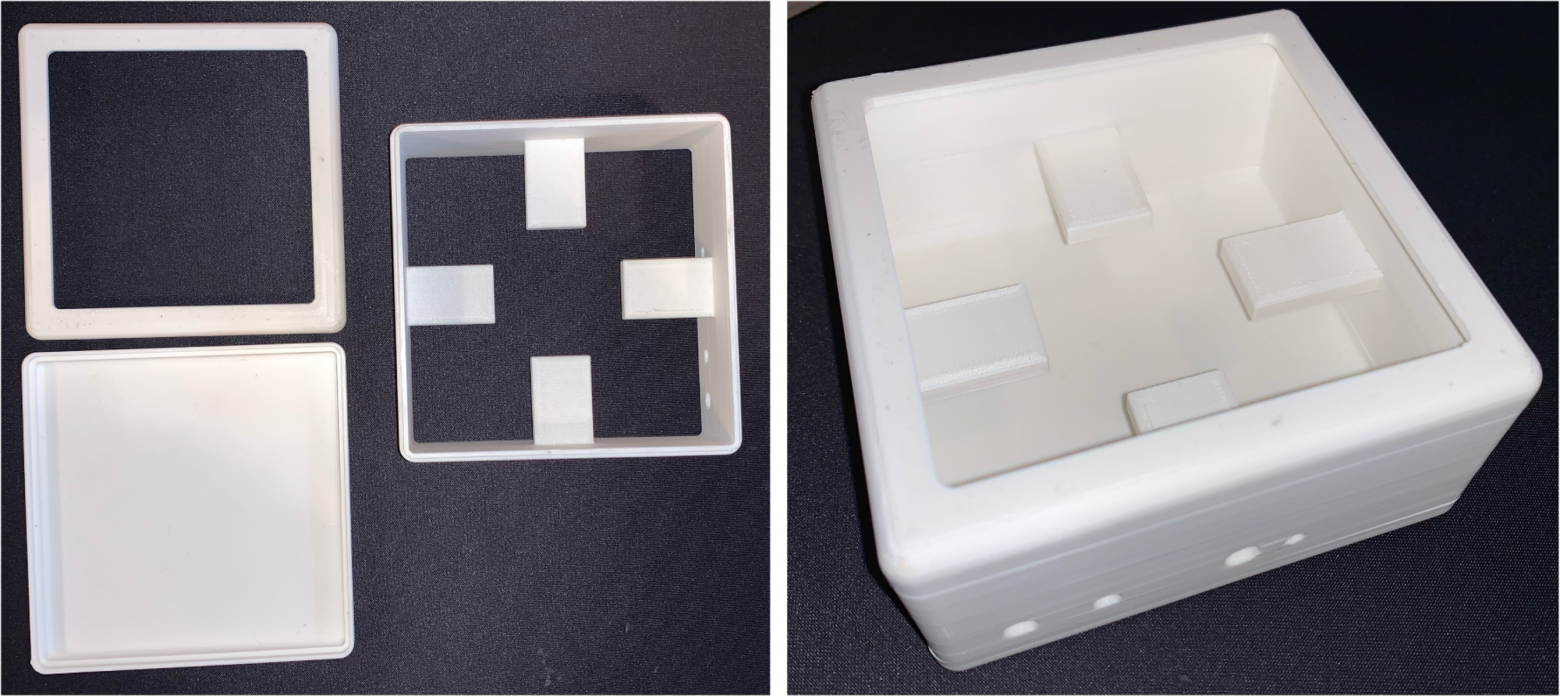
Printed SmartLight case in disassembled and assembled states
Final assembly of the device in the housing
Finally, I soldered and assembled all the hardware into a printed package. I would not like to consider this device a full-fledged one, so I prefer to think of it as a prototype of something more advanced and thoughtful, although I am unlikely to modify it in the future.
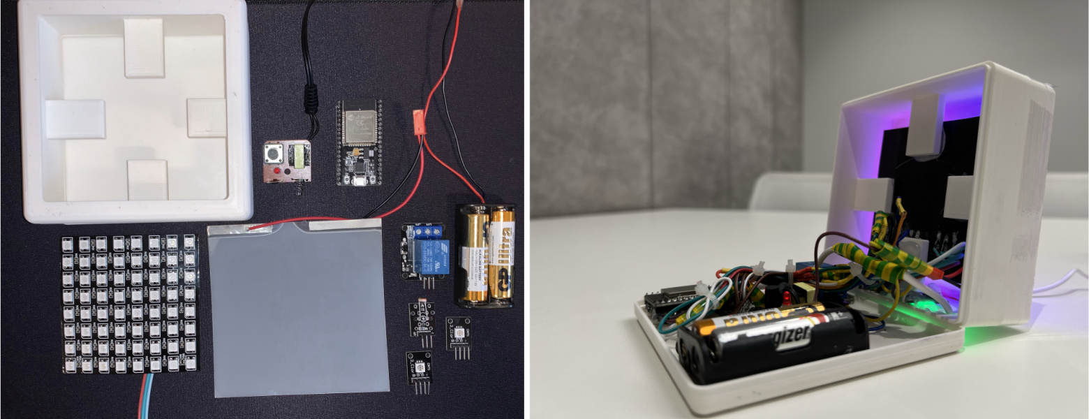
Device before and after installation of components
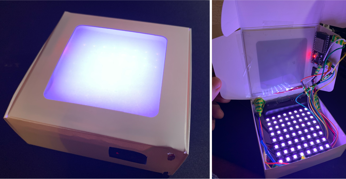
As mentioned earlier in this article, the functionality of the device itself will not be demonstrated here during its operation. This part will be covered in article , dedicated to writing a mobile application to interact with both Internet of Things devices (SmartLight and SmartPulse). But I think it is necessary to show photographs of the device turned on with a gradient glow effect with electrochromic film turned on and off.
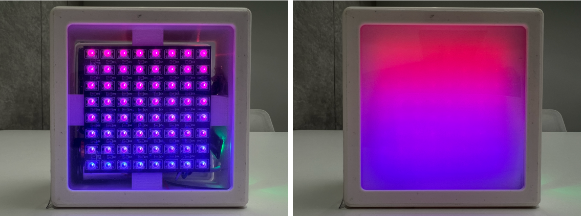
Sma rtLight in "Color Gradient" mode with electrochromic film on and off
B next part This series of articles will examine the process of creating a portable Internet of Things device “SmartPulse”, during the development of which the highest priority protection mechanisms from those proposed by me in previous article security techniques.
I am grateful to everyone who took the time to read this article. It would be incredibly cool to receive feedback in the form of comments in order to improve the quality of the material.
In the next parts...
Since the thesis turned out to be quite voluminous, I decided to break it into several related articles:
1. Information Security Specialist Diploma. Part No. 1 - Methodology for ensuring the security of Internet of Things devices
2. Diploma of information security specialist. Part No. 2 - Stationary SmartLight device
3. Information Security Specialist Diploma. Part #3 - SmartPulse portable device
4. Information Security Specialist Diploma. Part No. 4 - Smart Connect mobile application
5. Information Security Specialist Diploma. Part #5 - Unauthorized access to IoT devices with BLEWith the original VKR can be found here
Discussion
Comments
Comments are available only to confirmed email subscribers. No separate registration or password is required: a magic link opens a comment session.
Join the discussion
Enter the same email that you already used for your site subscription. We will send you a magic link to open comments on this device.
There are no approved comments here yet.