Essay
Information Security Specialist Diploma. Part #3 - SmartPulse Portable Device
A short preface Hello, Habr! This article is the third in the series “Diploma of an Information Security Specialist”, in which I talk about my experience in writing a final qualifying thesis for...
A short preface
Hello, Habr!
This article is the third in the series “Diploma of an Information Security Specialist,” in which I talk about my experience in writing a final qualifying thesis for the higher education program “Computer Security.” B previous article I described the process of developing a stationary IoT device “SmartLight” without implementing security mechanisms from the methodology for ensuring the security of Internet of Things devices, which I proposed in first part this series of articles. In the current article we will talk about the creation of a portable device "SmartPulse", the development of which included the implementation of the highest priority protection mechanisms of the technique.
If you have not had time to read the previous articles in this series, I advise you to read them first in order to better understand the context of what is happening.
SmartPulse portable device

Smart heart rate monitor based on the DALL-E neural network
After I assembled the stationary SmartLight device, I began to implement a second Internet of Things device.
According to my idea, the first device was supposed to be stationary, and the second was portable, in order to show different approaches to demonstrating devices during thesis defense (and I also wanted to use a small lithium-polymer battery that I had lying around). If the first device for me was the SmartLight smart lamp, then the second I planned to implement was the SmartPulse smart heart rate monitor.
SmartLight's goal was to demonstrate an Internet of Things device completely devoid of any security mechanisms. That is, recreating a situation where the developer did not think about the security of his device at all.
With the second device everything should have been different. SmartPulse had to fulfill the role of a sufficiently secure device. Moreover, it is protected by those mechanisms that were determined to be the highest priority through a mathematical model in the process of implementing the methodology for ensuring the security of Internet of Things devices. This device was supposed to be physical proof of the effectiveness of what I proposed. techniques . Therefore, I was tasked with creating a small, portable heart rate monitor that would transmit data via BLE to a smartphone and would still meet security requirements, combining the highest priority security mechanisms that I had previously identified.
Heart rate monitor concept with safety mechanisms
A heart rate monitor with built-in protection mechanisms sounds extremely inadequate. I am aware of this moment. It may seem that there is no point in ensuring the security of these types of devices. After all, then you can encrypt temperature data e water in a smart kettle, or information about the light level in the same SmartLight. But I would like to clarify my position.
The security problem of the Internet of Things is precisely that many people do not see the point in protecting at least a conventional smart refrigerator that is connected to home Wi-Fi (why does a refrigerator need an Internet connection at all is a question for debate), or a smart light bulb that you can control from your smartphone using the same BLE. And this is a big mistake.
On the Internet you can find a sufficient number of different stories about how hackers used a hacked IoT device to gain access to much more valuable user data (a small examplenews articleon this topic). Often, smart devices are not the ultimate goal of hacking, but are an opportunity to gain access to your smartphone, laptop, router or social media accounts. To something that may contain more valuable information than your heart rate or the temperature in your apartment. Therefore, the idea of implementing at least some minimal protection mechanisms in a smart chandelier in your kitchen or outlet is not without common sense. I also very often come across the fact that many people do not understand how and what information about them can be used to cause them any harm.
I don’t want to claim that my final version of protecting a smart heart rate monitor is the most correct and correct. The goal is different: to demonstrate how this can be done. At the moment I can only offer solutions, which is what I did infirst part.
With the concept of SmartPulse itself, in my opinion, everything is quite simple. I decided that I wanted this device to sit on the user's wrist and transmit data about their heart rate, as well as battery level (because the device is portable, and this is at least logical) to a small screen on the device itself and to a mobile application on the smartphone. Nothing complicated or unusual, as is the case with SmartLight and electrochromic film. I decided to keep it simple, since in addition to the functionality of the device, it was necessary to implement the protection mechanisms from the methodology.
Security SmartPulse
In terms of ensuring device security, I chose the following protection mechanisms:
-
Secure connection: BLE 5.0 specification module configuration configuration;
-
Data and firmware encryption;
-
Random number sequence generators: will be implemented using the library;
-
Restricting access to critical memory areas;
-
Limiting physical interaction: the device is implemented in the format of a wristband worn on the hand;
-
Distribution of encryption keyswhen pairing;
-
Limit on number of connections: software will be limited to one connection to the device;
-
Using the latest BLE specifications: a module that supports BLE 5.0 will be used;
-
Dynamic pin code for authentication: The PIN code will be updated every time the device is turned on;
I note that all of the above protection mechanisms belong to the “highest priority” class in the methodology I propose. A specialized case was not implemented due to the difficulties of working with flexible materials to be able to wear the device on the arm. It would have been possible to develop a plastic case as in the case of SmartLight, but I decided to do without it. Time was running out too much.
In this article I want to analyze in detail the pin code, the limit on the number of connections, physical interaction and the random (most likely pseudo-random) number generator, since I like the combination of mechanisms that were formed from them. In my opinion, I managed to make them work comprehensively, and therefore more efficiently.
I was guided by the following logic:
-
when the device is turned on, it is on the hand of the user who turns it on;
-
When the device turns on, a script is triggered to generate a random six-digit PIN code, which is displayed on the device screen for 5 seconds. This PIN code will not be sent anywhere else. It will be impossible to watch it in the future. That is, only the person who physically wears the device has access to it, and without this PIN code it will not be possible to receive data from the device in the mobile application;
-
If an attempt was made to connect to this device and read the BLE service characteristics values without entering an authentication PIN code, the device restricts further connection to it from a smartphone until SmartPulse is physically restarted. That is, this can be done by the user himself, who has a heart rate monitor on his wrist. In this case, when the device is restarted, a new 6-digit PIN code will be generated;
-
If a smartphone is already connected to this device, that is, data is sent via BLE, SmartPulse stops sending packets to other possible devices in the Bluetooth Low Energy coverage area. In other words, if the user’s smartphone is already connected to the heart rate monitor, it will not be displayed on other smartphones in principle. This means that in this case it may not be possible to connect to it while the device is already transmitting data to the application on the user’s smartphone.
In the last part of the articles in this series, I will demonstrate the NSD process for this device, where all of the above will be practically confirmed. I would also like to try to attack SmartPulse using my Flipper Zero and see for myself how much I can bypass the protection on it. If I have enough time to do all this, I will definitely write another article.
Hardware
Let's move on to the hardware of the device. I won’t invent anything new, so I’ll follow the same scheme as in the article about SmartLight.
To begin with, let's compare the class of an electronic component with its functionality. part of the device in order to understand what is, in principle, necessary to implement all its functions.
|
Electronic component |
Device functionality |
|---|---|
|
Microcontroller |
Device control and data transfer using BLE technology |
|
OLED display |
Displays battery charge and heart rate data, as well as briefly displays a random PIN code when the device is turned on for authentication during the pairing process |
|
Heart rate sensor |
Heart rate detection |
|
Voltage sensor |
Monitoring the voltage on the battery, on the basis of which its charge level is subsequently calculated |
|
Charge controller module |
Battery charging function |
|
Lithium polymer battery |
Self-powered device |
|
Touch sensor |
Turning the OLED display on and off |
|
Tact button |
Turning the device on and off |
The voltage sensor, charge module, battery and button are essentially part of one logical block, so let's look at them together.
Device power
SmartPulse is a portable device, which means it requires a battery. As I wrote earlier, I only had a 320 mAh lithium polymer battery on hand, so I decided to use that.
Lithium polymer (Li-Po) batteries are a type of lithium-ion battery that uses a polymer electrolyte instead of a liquid electrolyte. This technology was developed to improve performance and safety compared to traditional lithium-ion batteries.
This battery needed to be charged somehow, so I added a TP4056 type battery charge controller module to the circuit, which is an effective device for controlling the recharging of this kind of power supply. This module ensures optimal charging by adapting to the specific characteristics of the battery, and also has built-in overcharge and deep discharge protection functions that guarantee battery safety, preventing damage and ensuring reliable use (according to the manufacturer).
Since the device uses a battery, there is a need to know its charge level in order to recharge it on time. For these purposes, I decided to use the CJMCU-219 voltage and current sensor on the INA219 chip. To determine the battery charge level, I use the method of calculating the parameters of the current consumed by the battery and the voltage at its contacts, which is what the sensor records. In this way, it is possible to determine whether the battery is working at full capacity or not, based on which it is possible to draw conclusions about its charge level. Method far from accurate , and commercial products use other means, but nevertheless, it turned out to be working, and I didn’t need anything more as part of my thesis.
Naturally, SmartPulse had to be turned on and off somehow to save battery power Torah. So I added a button to the diagram. There is nothing to add about it, since it simply releases current to the microcontroller when the circuit is closed.
Information display
To display information about heart rate and battery charge, I decided to use a 0.96-inch OLED display with a resolution of 128x64 pixels. I don’t think there is any point in writing anything in particular detail about OLED technology or the display itself, since given that you are currently reading this article on the screen of your device, you have obviously heard about such things, and a deeper understanding is not required within the project.
I decided to add a touch sensor so that the user can turn the display on or off without turning off the device. This is necessary, for example, if the user does not currently need to record his pulse on his wrist while performing a workout, and his heart rate is monitored by a trainer using a smartphone.
Microcontroller
As the control board for the portable device, I chose WeAct Studio ESP32-C3Fx4 Mini Core, based on the ESP32-C3FH4 chip. The main factor for this solution is the implementation of a newer version of BLE compared to the microcontroller in the SmartLight device. Also, the size of the microcontroller played a certain role in favor of choosing this chip and this particular board.
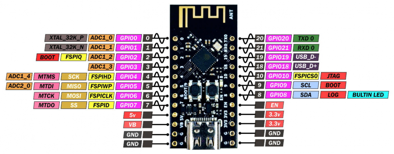
Pinout WeAct Studio ESP32-C3Fx4 Mini Core
Component connection diagram
After all the necessary electronic components for the future device were selected, I developed a diagram for connecting them to the microcontroller board.
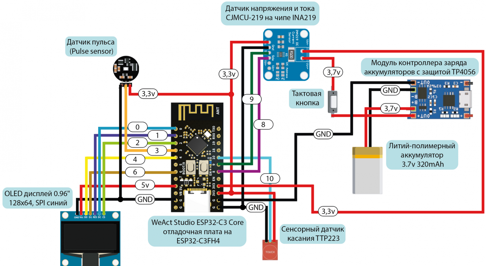
Electronic components connection diagram
The stage with the implementation of this circuit on a breadboard, as in the case of the previous device, will have to be omitted, because I have a bad habit of not taking photographs of breadboards.
Software part
Just as in the case of a stationary device, after assembling the circuit on a breadboard, I began writing the software part of the device.
Development environment and programming language
There are clear differences between the devices here. Let me remind you that to program SmartLight I used the Arduino IDE and the version of C++ that is integrated into it. To write the SmartPulse software, it was necessary to go down one level to implement protection mechanisms and most effectively use the capabilities of the ESP32-C3.
To make this a reality, I decided to use the development environment ESP-IDF , which is ideal for the ESP series microcontrollers (because it was written for them), as well as the C programming language. I won’t write in detail about ESP-IDF, so I’ll just leave it link to the official documentation.
In order to start using this development environment for writing firmware, you need to connect the microcontroller to the computer and select
corresponding COM port. After selecting a port and creating a repository with firmware, you can download the code to the device using the command
idf.py flash
after preliminary assembly of the project.
If anyone needs to read about the development environment in a little more detail and understandably, I’ll leave it here tutorial . But in general, I advise you to read the official documentation (painful, but useful).
Firmware
Just like in the case of a stationary device, I don’t see the point of posting the full code of the device here. It is available in applications VKR and in the SmartPulse project repository at GitHub . In this article, we will analyze only the key points of implementing security mechanisms and the most basic code fragments.
I propose to again break the code into structural blocks according to functionality:
|
Structural block |
Purpose and functionality |
|---|---|
|
Connecting libraries |
Import of standard C libraries and specialized libraries for FreeRTOS, ESP32, BLE |
|
Definition of Constants and Variables |
Declaring Global Variables |
|
BLE functionality |
Configure and manage BLE server and features, use NimBLE stack on ESP32 to manage connections and handle BLE events |
|
Display |
Working with an OLED display via the SSD1306 library |
|
Processing data from the heart rate monitor |
Reading and processing heart rate data through, filtering and averaging signals |
|
Processing battery charge level data |
Measuring battery voltage, calculating its charge level |
|
Processing touch sensor data |
Turn the display on or off based on touch sensor data |
|
Security |
Implementation of security mechanisms: generating a random PIN code, setting BLE security parameters, access to heart rate and battery charge data only for authenticated users |
The first block includes standard C libraries:
stdio.h
,
stdlib.h
and
string.h
, which provide basic functions for I/O, memory and strings, as well as specialized libraries for working with FreeRTOS, ESP32 and BLE:
freertos/FreeRTOS.h
,
freertos/task.h
,
esp_log.h
,
driver/i2c.h
,
driver/adc.h
,
driver/gpio.h
, and so on.
To work with Bluetooth Low Energy on the ESP32, the ESP-NimBLE libraries are used. This framework is a port of the NimBLE stack, adapted to work with ESP32 family chips. Main library
esp_nimble_hci.h
Provides Host Controller Interface (HCI) functionality, allowing interaction with a Bluetooth controller at this level.
To integrate the NimBLE stack with the FreeRTOS operating system and
libraries are used
nimble/nimble_port.h
and
nimble/nimble_port_freertos.h
.
Library
host/ble_hs.h
is the main tool for working with the NimBLE stack at the host level. It includes functions for BLE state management, such as connection and distribution management. For management
GAP
andGATT
are used accordingly
services/gap/ble_svc_gap.h
and
services/gatt/ble_svc_gatt.h
.
For those who are scared by the abbreviations GAP, GATT, SMP, etc., I leave link to analyze the BLE technology protocol stack.
This device implements the highest priority protection mechanisms from the security methodology, but we will consider in detail those that work most effectively in combination: generation of a random PIN code, as well as mechanisms to ensure access to data only by authenticated users.
To increase the security of the connection between devices, a method of generating a random PIN code is used. To generate a random (or still pseudo-random) sequence, I decided to use the library
esp_random.h
. I implement the capabilities of this library using the function
generate_random_passkey
, which generates a six-digit code to authenticate the user.
void generate_random_passkey()
{
    uint32_t random_num = (esp_random() % 900000) + 100000; // Generate a random number
    snprintf(passkey, sizeof(passkey), "%06lu", random_num); // Formatting a number into a string
    ESP_LOGI(TAG, "Generated passkey: %s", passkey); // Logging the generated code
}
This combination must be entered on the connected device to be able to read the heart rate characteristics and battery charge level. The randomness of the PIN code makes potential unauthorized access attempts much more difficult, since each new connection requires a new password to be entered.
As you can see in the code fragment being analyzed, I cheated a little and instead of implementing 1,000,000 different PIN code variations from 000000 to 999999, I actually use combinations from 100000 to 999999. This reduces the number of possible options, but this solution does not affect the security of the device, since the generated code must be entered immediately after turning on the device, and after successful pairing with the smartphone, SmartPulse will no longer be available to connect to it from any other devices, which makes it pointless to try different PIN code combinations for authentication.
Next, this pin code will be stored in a variable
passkey
. When the user is required to enter a password during the pairing process, he will essentially make an entry to the device's BLE characteristic value, which will be compared with
passkey
. Based on this action, authentication will be performed.
I had to implement it head-on, but for good measure, I would still recommend using at least some kind of lightweight cryptography or just hashing like new things. There should not be such obvious checks of authentication combinations. This method is still unsafe in itself, but when there is not enough time for more complex protection (exactly my case), you can at least implement it this way.
static int device_write_pincode(uint16_t conn_handle, uint16_t attr_handle, struct ble_gatt_access_ctxt *ctxt, void *arg)
{
    size_t om_len = OS_MBUF_PKTLEN(ctxt->om); // Get packet length from GATT context
    char pincode[7]; // Array for storing the pin code
    // Convert data from mbuf to array
    int rc = ble_hs_mbuf_to_flat(ctxt->om, pincode, sizeof(pincode) - 1, &om_len);
    if (rc != 0) {
        return BLE_ATT_ERR_INVALID_ATTR_VALUE_LEN; // Return error
    }
    pincode[om_len] = '\0';

    if (strcmp(pincode, passkey) == 0) { // Compare the received pin code with the saved one
        is_authenticated = true; // Set the authentication flag if successful
	 // Log successful authentication
        ESP_LOGI(TAG, "Authenticated with pincode: %s", pincode);
    } else {
        is_authenticated = false; // Reset the authentication flag if there is a mismatch
        ESP_LOGE(TAG, "Invalid pincode: %s", pincode); // Log the error
    }

return 0; // Return 0 if the function was processed successfully
}
After the user writes the authentication pin code in the mobile application, the flag is checked
true
or
false
in the characteristics of heart rate values and battery charge level. The transfer of variables into characteristic values occurs only after checking the value of the authentication flag.
I will say again that I would not recommend performing such operations explicitly, since if you try to find an opportunity to change the value of the flag itself
is_authenticated
, you can access the transmitted information without entering a PIN code at all, which should not happen under any circumstances. I implemented it this way because I was developing a device for an experimental stand as part of my thesis under conditions of severe time constraints. If we are talking about the development of a commercial product, even within the framework of a conventional startup and with a relatively small team, I
I don't recommend it at all
do as I did.
Let me remind you that the goal of my work is to demonstrate a new approach to securing IoT devices based on calculating priority metrics for security mechanisms using a mathematical model within limited development resources, and not to implement a perfect secure development cycle for an IoT device (although I would really like to).
static int device_read_Pulse(uint16_t conn_handle, uint16_t attr_handle, struct ble_gatt_access_ctxt *ctxt, void *arg)
{
    if (!is_authenticated) { // Check authentication status
        return BLE_ATT_ERR_INSUFFICIENT_AUTHEN; // Return error
    } else {
	 // Adding the heart rate value to the transmission buffer
        os_mbuf_append(ctxt->om, &Pulse, sizeof(int));
        return 0; // Return 0, indicating success
    }
}

static int device_read_Bat(uint16_t con_handle, uint16_t attr_handle, struct ble_gatt_access_ctxt *ctxt, void *arg)
{
    if (!is_authenticated) { // Check if the user is authenticated
        return BLE_ATT_ERR_INSUFFICIENT_AUTHEN; // Return error
    }
    else {
	 // Add battery charge value to transfer buffer
        os_mbuf_append(ctxt->om, &Bat, sizeof(int));
        return 0;
    }
}
As described earlier, I used the OLED display of the device itself to display the authentication pin code so that the code would initially only be visible to the wearer of the device. Each time you turn on the device, the PIN code is generated anew and displayed for 5 seconds on the SmartPulse display.
The code for displaying the PIN code on the device display with a delay of 5 seconds can be seen below.
  ssd1306_clear_screen(&dev, false); // Clean OLED display screen
  ssd1306_contrast(&dev, 0xff); // Set screen contrast
  ssd1306_display_text(&dev, 0, "PIN", 3, false); // Display the text "PIN" on the screen
  ssd1306_display_text(&dev, 2, passkey, 6, false); // Display the generated pin code
  vTaskDelay(5000 / portTICK_PERIOD_MS); // Delay for 5 seconds
  ssd1306_clear_screen(&dev, false); // Clear screen after delay
A limitation on the possible number of connections to the SmartPulse device has been implemented in the ESP-IDF configuration menu by
sdkconfig
(you can use the command
idf.py menuconfig
, here who likes what more). Since this project uses BLE technology, you need to turn on Bluetooth in the settings and set the NimBLE mode to BLE only. Some BLE security settings are also implemented here.
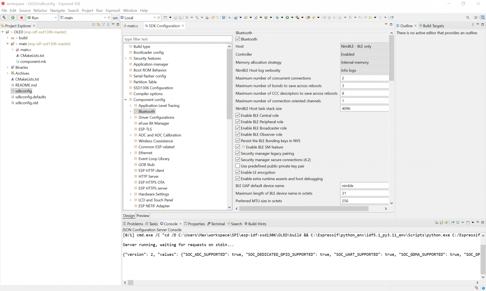
Contents of sdkconfig
Let's move on to implementing BLE in the device code. I have already demonstrated some fragments related to Bluetooth Low Energy at the stage of parsing the pin code. We will not return to them. If you remember how the code was written to implement BLE in SmartLight, you can understand that, in essence, you need to set a BLE server, which you need to give a name that is displayed in the list of devices available for connection. This is the device profile. In this case, the server will be initialized as follows.
  nimble_port_init(); // Initialize the NimBLE port
  ble_svc_gap_device_name_set("SmartPulse"); // Set the device name
  ble_svc_gap_init(); // Initialize GAP for Bluetooth
  ble_svc_gatt_init(); // Initialize GATT for Bluetooth
  rc = ble_gatts_count_cfg(gatt_svcs); // Counting GATT service configurations
  assert(rc == 0); // Check the success of the counting operation
  rc = ble_gatts_add_svcs(gatt_svcs); // Adding GATT services
  assert(rc == 0); // Check the success of the add operation
  ble_hs_cfg.sync_cb = ble_app_on_sync; // Set the callback function
  nimble_port_freertos_init(host_task); // Initialize NimBLE using FreeRTOS
Next, services must be created that will store characteristics with three available properties, values and descriptors. We will implement this stage in a similar way for SmartPulse.
static const struct ble_gatt_svc_def gatt_svcs[] =
{
    {
        .type = BLE_GATT_SVC_TYPE_PRIMARY, // Service type
        .uuid = BLE_UUID16_DECLARE(0x180), // Service UUID
        .characteristics = (struct ble_gatt_chr_def[]){ // Array of service characteristics
            {
                .uuid = BLE_UUID16_DECLARE(0xFEF3), // UUID characteristics for the pin code
                .flags = BLE_GATT_CHR_F_WRITE, // Characteristic properties: write only
                .access_cb = device_write_pincode, // Callback function
                .val_handle = &auth_handle, // Pointer to value handle
            },
            {
                .uuid = BLE_UUID16_DECLARE(0xFEF4), // UUID characteristics for the pulse
                .flags = BLE_GATT_CHR_F_READ | BLE_GATT_CHR_F_NOTIFY, // Read and notify
                .access_cb = device_read_Pulse, // Callback function for reading pulse
                .val_handle = &pulse_val_handle, // Pointer to pulse value handle
            },
            {
                .uuid = BLE_UUID16_DECLARE(0xFEF5), // UUID characteristics for battery charge
                .flags = BLE_GATT_CHR_F_READ | BLE_GATT_CHR_F_NOTIFY, // Read and notify
                .access_cb = device_read_Bat, // Callback function
                .val_handle = &bat_val_handle, // Pointer to a handle to the battery charge value
            },
            {0}, // Resetting the characteristics array
        },
    },
    {0}, // Resetting the array of services
};
The function that is required directly to send the values of the battery charge level and heart rate variables can be specified as follows:
void ble_notify(uint16_t attr_handle, int value)
{
    if (!is_authenticated) { // Check if the user is authenticated
        return; // Exit the function if the user is not authenticated
    }
    else {
	 // Create a message buffer from a value
        struct os_mbuf *om = ble_hs_mbuf_from_flat(&value, sizeof(value));
	 // Send a notification using the changed value
        int rc = ble_gattc_notify_custom(conn_handle, attr_handle, om);
        if (rc) {
            ESP_LOGE(TAG, "Error sending notification; rc=%d", rc); // Log the error
        }
    }
}
It is this function with parameters that we subsequently call when the device is operating to change the values in the corresponding characteristics of the BLE service.
if (conn_handle != 0){ // Check for an active BLE connection
  ble_notify(pulse_val_handle, Pulse); // Send heart rate notification
  ble_notify(bat_val_handle, Bat); // Send notification about battery level
}
At this point I propose to finish analyzing the code. Fragments of code for the pulse sensor, the formula for calculating battery charge, etc. can be seen explicitly in the full firmware on GitHub . I I tried to leave as detailed comments on the code as possible to make it easier to perceive and analyze (in my life I have never written so many comments as in the framework of this thesis).
Housing
I decided not to make a housing for SmartPulse as such. I didn’t want to try to make an analogue of a fitness tracker or smart watch, layering boards on top of each other. It was important for me to provide myself with access to all the electronic components of the device so that I could replace or resolder them if something happened. In addition, I wanted the entire implementation of the scheme, which I had already posted in this article, to be clearly demonstrated on my wrist during the defense of my final qualifying thesis. Therefore, I decided to use a fairly simple method - attach all the boards to a fabric wristband
Nike
one famous sports brand, named after the Greek goddess of victory, Nike, which I bought specifically for this purpose.
I didn't want to sew on the boards themselves, because it was at least inconvenient. For example, it would be problematic to sew the same touch sensor onto a wristband, since its board does not even have a hint of any holes or fasteners that would allow me to do something like that. So I found another way out of this situation and bought Velcro strips.
I acted from the logic that you don’t have to sew the boards themselves to the wristband, and to attach them it will be enough to sew only Velcro, onto which you will already need to attach the board with the tenacious part of the Velcro. In the end, that's what I did. Since my sewing skills leave much to be desired, I am incredibly grateful to Anya ( @ShabrovaAS ), who did this process for me.
It’s very convenient when your girlfriend knows how to draw (which helped in preparing the body drawings for SmartLight) and sew (which made my life easier already as part of preparing the wristband for SmartPulse).
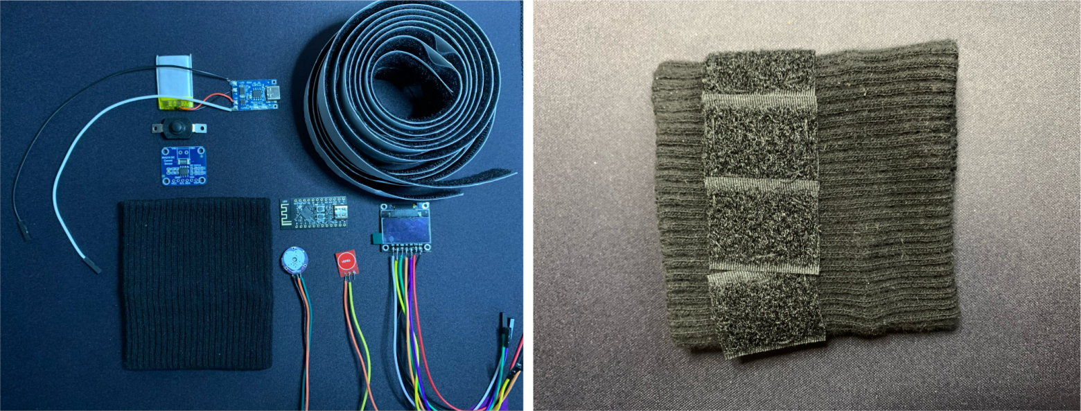
The device before installing the components and the prepared base of the wristband
Final assembly of the device
After the wristband was ready to mount all the electronic components on it, I started soldering. This was a rather long stage, since soldering was not particularly convenient, and the contacts were very close to each other (sorry for the not very careful soldering). But in the end I was able to assemble the final version of SmartPulse.
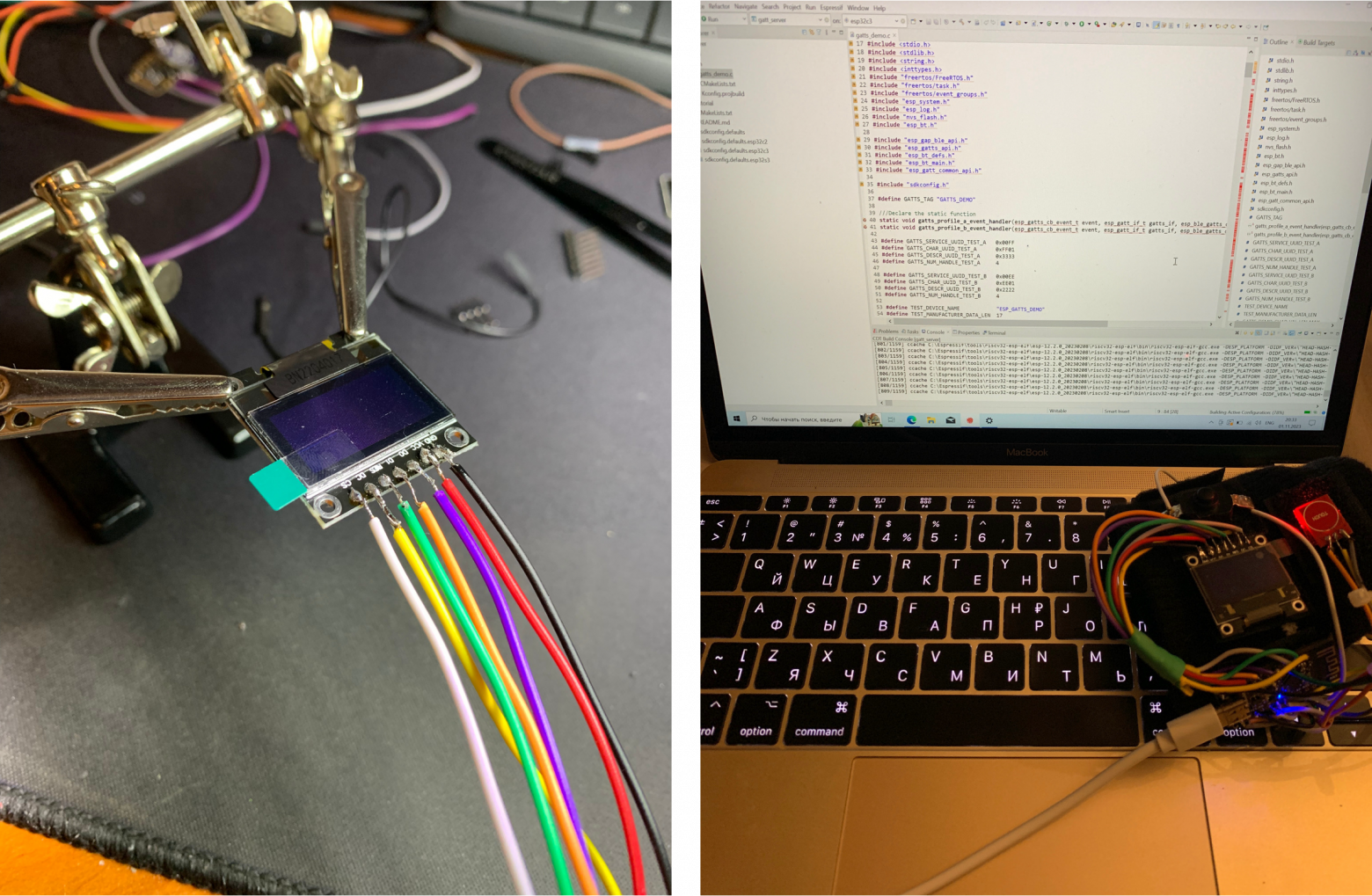
The process of soldering electronic components and firmware of the finished device
As with the SmartLight, I don’t want to call it a finished device and prefer the word “prototype.” Because in my personal opinion, the finished device cannot look like a wristband with chips attached to it. In any case, this was more than enough to demonstrate this type of device as part of my thesis defense, and I was satisfied with the result.
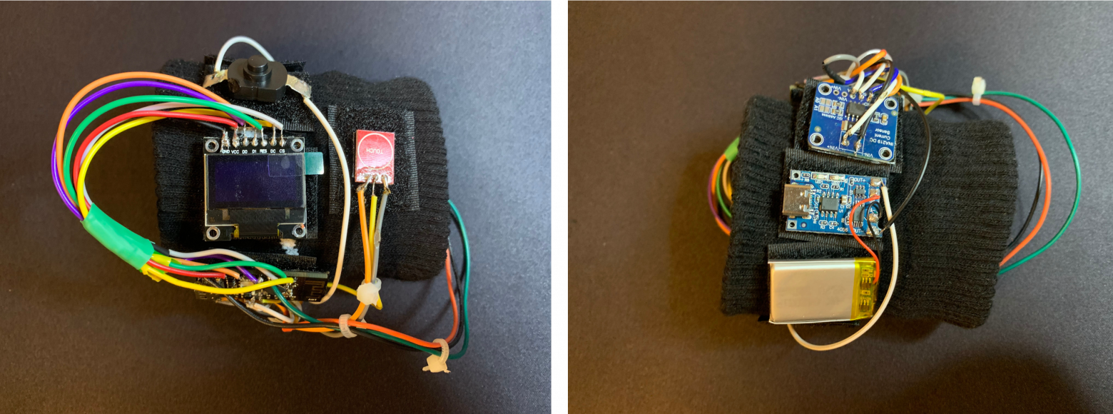
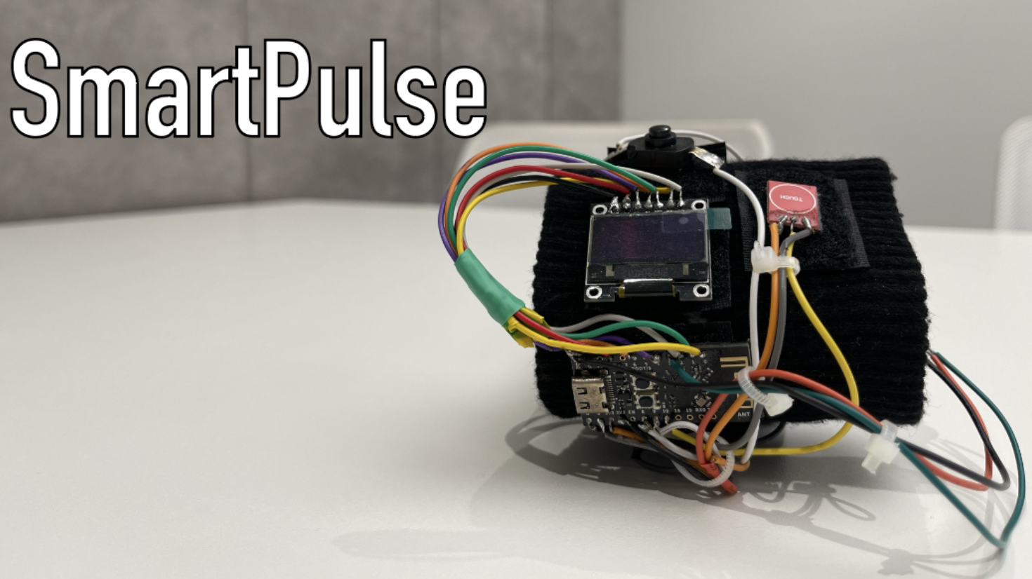
Assembled SmartPulse device
As I already mentioned, the article will not demonstrate the functionality of the device itself during its operation. This part will be covered in the next article. This article will discuss the process of creating a mobile application to control the SmartLight and SmartPulse Internet of Things devices created in the previous parts. But in order to still show exactly what a working SmartPulse device looks like on my wrist, I am attaching photos demonstrating this.
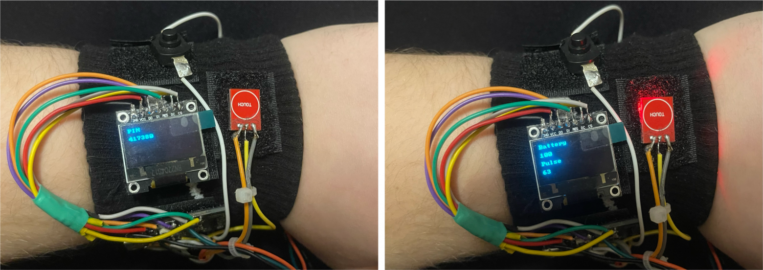
Generating a dynamic PIN code when the device is turned on and displaying heart rate and battery charge indicators on the screen
Bnext part This series of articles will discuss the process of creating a Smart Connect mobile application to manage the previously created SmartLight and SmartPulse IoT devices.
I am grateful to everyone who took the time to read this article. I would be incredibly happy to receive feedback in the form of comments in order to improve the quality of the material.
What's next?
Since the thesis turned out to be quite voluminous, I decided to break it into several related articles:
1. Information Security Specialist Diploma. Part No. 1 - Methodology for ensuring the security of Internet of Things devices
2. Information Security Specialist Diploma. Part No. 2 - Stationary SmartLight device
3. Diploma of information security specialist. Part #3 - SmartPulse portable device
4. Information Security Specialist Diploma. Part No. 4 - Smart Connect mobile application
5. Information Security Specialist Diploma. Part #5 - Unauthorized access to IoT devices with BLEWith the original VKR can be found here
Discussion
Comments
Comments are available only to confirmed email subscribers. No separate registration or password is required: a magic link opens a comment session.
Join the discussion
Enter the same email that you already used for your site subscription. We will send you a magic link to open comments on this device.
There are no approved comments here yet.