Essay
How to turn a toy delivery robot into a wirelessly controlled rover using a mobile app
Hello, Habr! Do you often get bored? Well, you just don’t know what to do with yourself anymore. At such moments, I like to scroll aimlessly through the feed, get stuck on different videos, and also scroll through marketplaces in the hope of seeing something that I could catch on to.
I want to buy such a rover, what should I do?
Six months have passed since the publication of this article. Absolutely different people began actively writing to me asking me to modify a toy rover to order for them. I have already completed a series of orders with pleasure and continue to do so to this day.
If you would like to purchase the same controllable rover, write to me in a telegram (
https://t.me/MaxiEnergy
), and he will go to you)
Hello, Habr!
Do you often get bored? Well, you just don’t know what to do with yourself anymore. At such moments, I like to scroll aimlessly through the feed, get stuck on different videos, and also scroll through marketplaces in the hope of seeing something that I could catch on to.
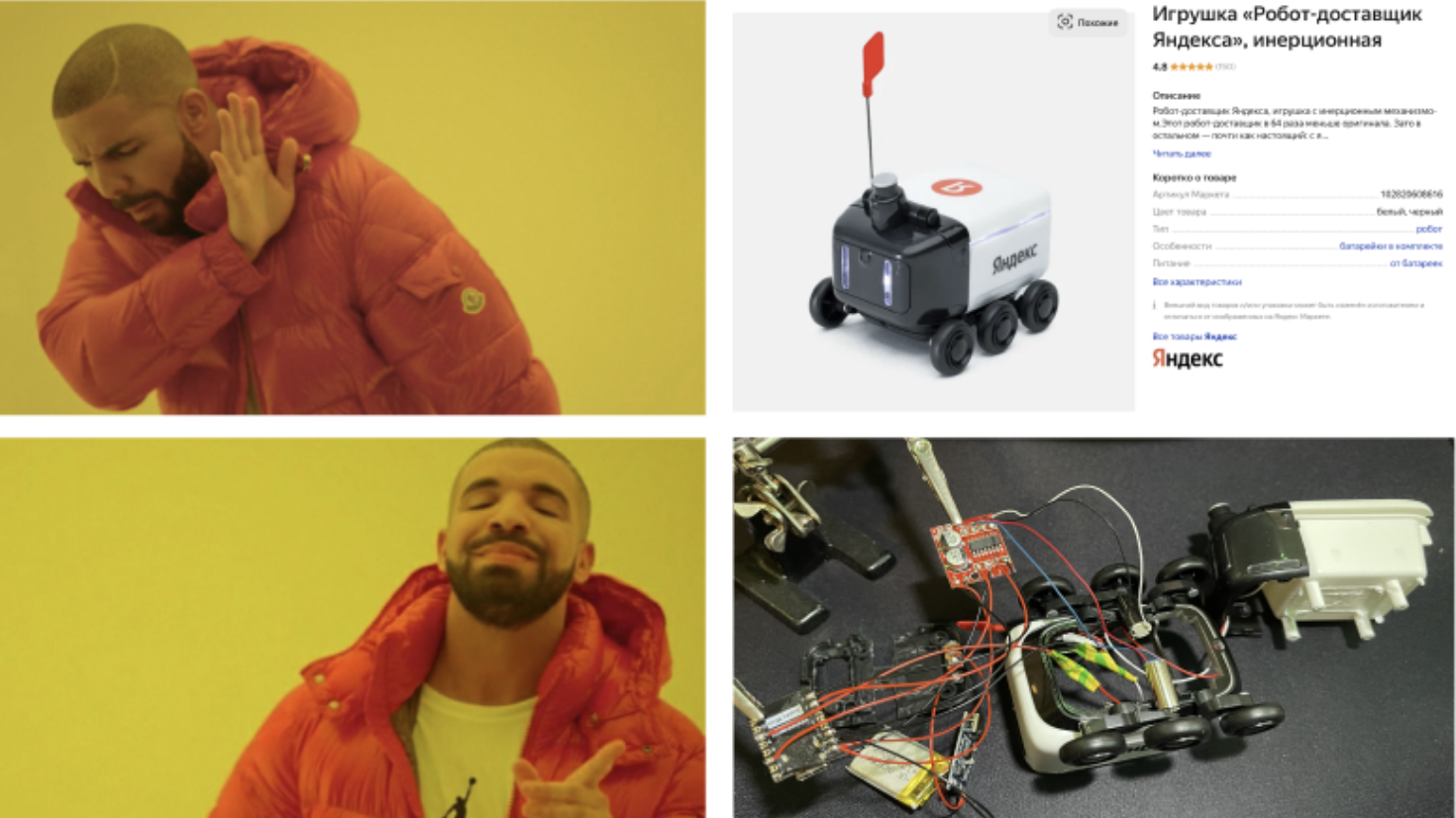
At one of these moments, while regularly browsing the contents of Yandex Market, I came across a toy robot courier. I thought it was cute enough so I decided to buy it.
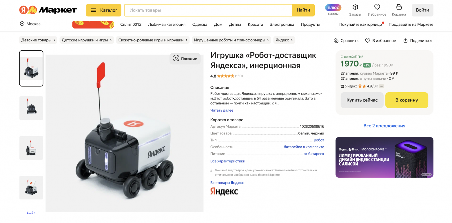
Toy on Yandex Market
Delivery robot
The model is made in the form of a real Rover 3 from Yandex in 1/64 scale. The inertial mechanism makes it a small toy that works on the principle of children's cars, which, most likely, everyone had in wonderful times of bluer skies and greenest grass.
Operation of the inertial mechanism
Also inside the robot there are LEDs to illuminate its “eyes” and the perimeter of the container, which, by the way, opens. All its glory runs on 3 LR44 batteries.
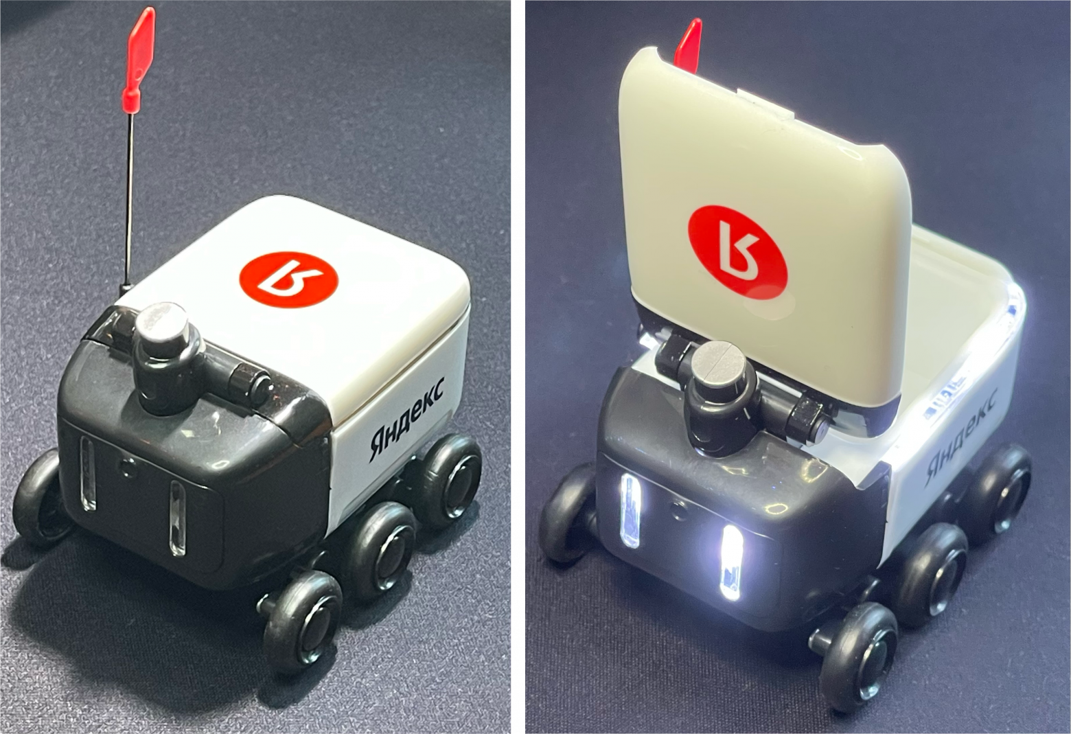
Rover illumination
In general, the rover is cute, well made, and I could have stopped here, but one thought flashed through my head...
Or maybe make it manageable?
Why should you be content with only what you have in the box? After all, it would be great to modify this rover so that it could be controlled. From that moment on, my head was busy trying to figure out what exactly I wanted from the poor toy.
In fact, it's simple. About the same as making a radio-controlled car out of an inertial car. But why radio control if you can write a mobile application and control it from your phone?
In the end I decided to do the following:
-
Control of the rover should be implemented using a mobile application on iOS, which I will write in Flutter (you can read about my first experience with this framework in the article about Smart Connect )
-
Wireless data transfer will be carried out using BLE, because I previously dealt with it (you can read the articles about SmartLight and SmartPulse ) and I consider it ideal for such projects (IMHO)
-
The rover must drive forward, backward, turn left and right, and also turn on the backlight ku by button in the mobile application
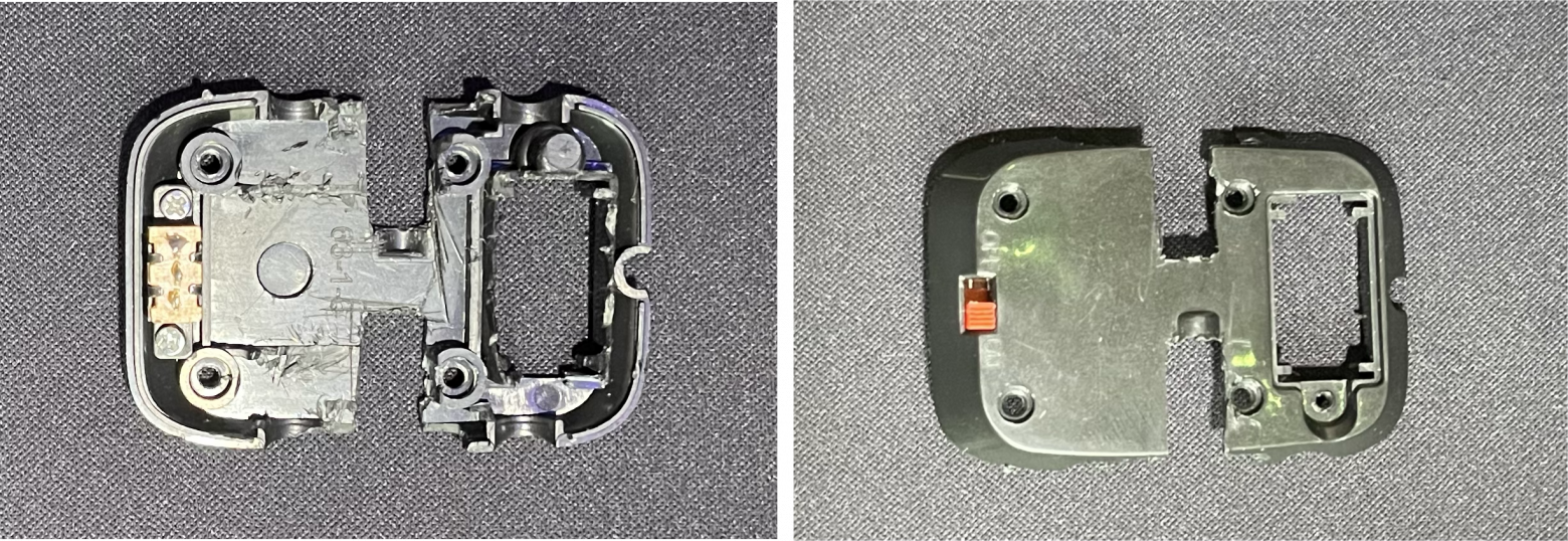
Next, I decided to disassemble the robot to understand how much space I could have inside it.

Inside the toy
There wasn't much space, but if you cut out some of the fasteners that were unnecessary for the project, it should be enough to accommodate all the necessary electronic components. Speaking of them.
What about the filling?
To implement the rotation of the rover, two small motors were needed. Similar classes of vehicles turn by simultaneously rotating the wheels in different directions. Real robot couriers, Mars rovers, and many other rovers work on this principle. That is, to turn right, it is necessary that the rover wheels on the left side of the body rotate forward, and the wheels on the right side rotate backward (if we talk about the direction of movement). Essentially, at this point the wheels are spinning either clockwise or counterclockwise at the same time. And to go forward or backward, one of the wheels must spin clockwise and the other counterclockwise, but we digress.
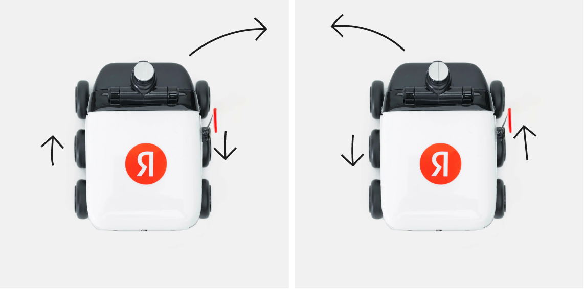
Diagram of the direction of wheel movement when turning the rover
To control the motors you need a driver. Naturally, since we are dealing with a small toy body, all the boards had to be selected as miniature. No sooner said than done, and I already had the L298N mini driver. It was possible to immediately solder two motors onto it, which I was incredibly happy about.
The rover's native batteries for two small motors with high torque would not be enough (I checked this experimentally), so I decided to use a 350 mAh battery and a charging board for it. According to my idea, all this should have been located in the place of the rover's battery compartment - in its head. There was enough space to place the battery, and you could also easily access its charging board through the compartment lid to charge the robot in the future.
What will manage all this? To work with BLE, there is an extremely successful line of ESP32 controllers with various modifications. Since in this project we are limited to a relatively small space for mounting the boards inside the device, I chose the ESP32-C3 SuperMini, which is no larger in size than the battery charging board.
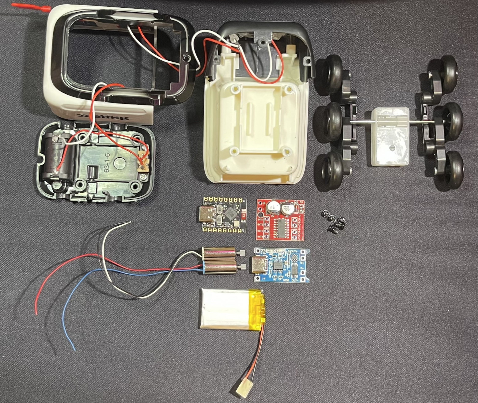
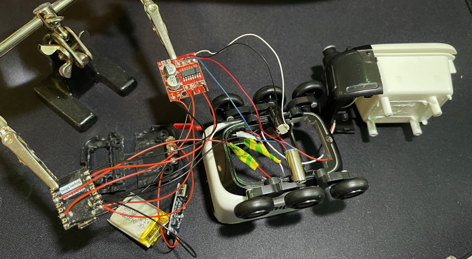
A disassembled rover and everything that needs to be put into it
In order to properly check all the modules and test the future firmware code, I implemented a diagram for connecting electronic components. In the future, components will be soldered in accordance with this diagram.
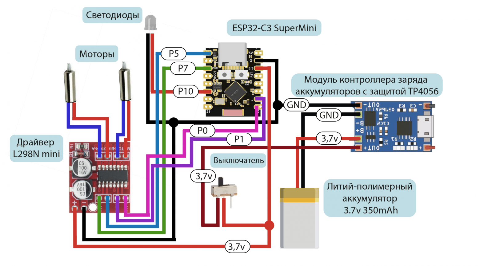
Electronic components connection diagram
Robot firmware
Let's move on to the rover firmware, the full version of which is in my repositories on GitHub (guests are always welcome).
Essentially, all we need to implement data transfer to the rover is to set up a BLE server and define a service and characteristic to which we will send values to turn the motors on and off. I wrote code in Arduino IDE using libraries
BLEDevice.h
,
BLEUtils.h
and
BLEServer.h
We initialize work with BLE using the following code:
BLEDevice::init("Yandex Delivery Robot");
pServer = BLEDevice::createServer();
pServer->setCallbacks(new MyServerCallbacks());
BLEService* pMoveService = pServer->createService(BLEUUID((uint16_t)0x170D));
pMoveCharacteristic = pMoveService->createCharacteristic(BLEUUID((uint16_t)0x2A60), BLECharacteristic::PROPERTY_READ | BLECharacteristic::PROPERTY_WRITE);
pMoveCharacteristic->setCallbacks(new MoveCharacteristicCallbacks());
pMoveService->start();
BLEAdvertising* pAdvertising = pServer->getAdvertising();
pAdvertising->addServiceUUID(pMoveService->getUUID());
pAdvertising->setScanResponse(false);
pAdvertising->setMinPreferred(0x06);
pAdvertising->setMinPreferred(0x12);
BLEDevice::startAdvertising();
Here we define the name of the device, and also assign a UUID to our service and characteristic
pMoveCharacteristic
Recording in characteristics is done using
MoveCharacteristicCallbacks
, in which I implemented a switch-case construction. A trimmed fragment is attached below.
class MoveCharacteristicCallbacks : public BLECharacteristicCallbacks {
    void onWrite(BLECharacteristic* pCharacteristic) {
        std::string value = pCharacteristic->getValue();
        if (value.length() > 0) {
            switch (value[0]) {
                case 0x01: // Rotate the rover left
                    ledcWrite(CHANNEL_IN1, 255);
                    ledcWrite(CHANNEL_IN2, 0);
                    ledcWrite(CHANNEL_IN3, 255);
                    ledcWrite(CHANNEL_IN4, 0);
                    break;
                case 0x02: // Rotate the rover to the right
                    ledcWrite(CHANNEL_IN1, 0);
                    ledcWrite(CHANNEL_IN2, 255);
                    ledcWrite(CHANNEL_IN3, 0);
                    ledcWrite(CHANNEL_IN4, 255);
                    break;
            }
        }
    }
}
Mobile application
Let's not stray too far from the code, so let's move on to writing a mobile application in Flutter. B repositories I posted its full version on GitHub, and here I’ll tell you about the main things.
The logic of the mobile application code, just like in the case of the firmware code, is built on a switch-case design. I decided to place buttons on the rover control page in the form of directional arrows (forward, backward, left, right) and a backlight on/off button in the form of a burning light bulb. When the user presses any of the direction buttons, the corresponding value is written to the BLE characteristic of the connected device (for example, for the rover to turn left - 0x01, for the rover to turn right - 0x02, etc.).
Positioned(
  bottom: 160,
  left: 80,
  child: controlButton(Icons.arrow_back, 0x01, "Left"),
),
Positioned(
  bottom: 160,
  right: 80,
  child: controlButton(Icons.arrow_forward

, 0x02, "Right"),
)
As soon as the user releases the button, the value 0 is written to the characteristic, through which one of the switch cases is turned on in the rover firmware and all motors are turned off. This way, the robot will drive when the direction button is pressed, and as soon as it is released, the rover will stop.
onPointerDown: (_) => sendCommand(command),
onPointerUp: (_) => sendCommand(0)
The backlight turns on when you press the button with the light bulb once. When you press it again, the backlight will turn off. Essentially it’s just a button that remembers its state.
Positioned(
  bottom: 40,
  right: 20,
  child: FloatingActionButton(
    onPressed: () {
      setState(() {
        toggleState = !toggleState;
        sendCommand(toggleState ? 3 : 6);
      });
    },
    child:Icon(
      toggleState? Icons.lightbulb_outline : Icons.lightbulb,
      color: Color.fromRGBO(255, 53, 63, 1),
    ),
    backgroundColor: Colors.white,
  ),
)
To work with BLE, I connected
flutter_blue: ^0.8.0
, and the process of connecting to the device is based on determining the distribution from a specific BLE server by its name. Values are recorded using the UUID of the service and the characteristics of the rover.
List services = await widget.device.discoverServices();
var targetService = services.firstWhere((service) =>
    service.uuid == Guid('0000170D-0000-1000-8000-00805f9b34fb'));
var targetCharacteristic = targetService.characteristics.firstWhere(
    (characteristic) =>
        characteristic.uuid ==
        Guid('00002A60-0000-1000-8000-00805f9b34fb'));
await targetCharacteristic.write(value);
After I tested the functionality of the application with a microcontroller, I wanted to somehow “bring it to mind” so that at least the application would look a little more prettier. On the rover control page there were only four buttons for controlling the motors and one button for the backlight. It looked a little boring, so I wanted to add some dynamics. I decided to draw models with the direction of the rover in Adobe Illustrator.
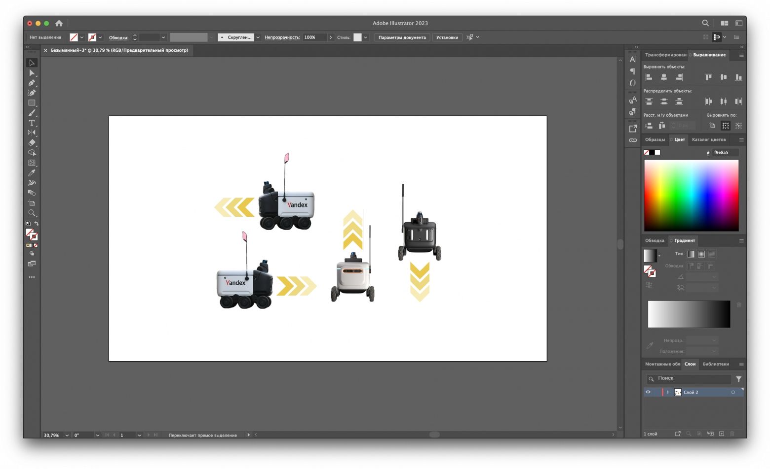
Images of the rover's direction
I implemented updating images by clicking on the corresponding rover control buttons, also via switch according to the value sent from the button.
setState(() {
  switch (command) {
    case 0x01:
      currentImage = 'assets/Left.png';
      break;
    case 0x02:
      currentImage = 'assets/Right.png';
      break;
    case 0x05:
      currentImage = 'assets/Forward.png';
      break;
    case 0x04:
      currentImage = 'assets/Back.png';
      break;
    default:
      break;
  }
});
Next, I selected the original Yandex red color for the interface and drew an application icon to complete the development of the mobile application and switch to installing all the electronics inside the rover.
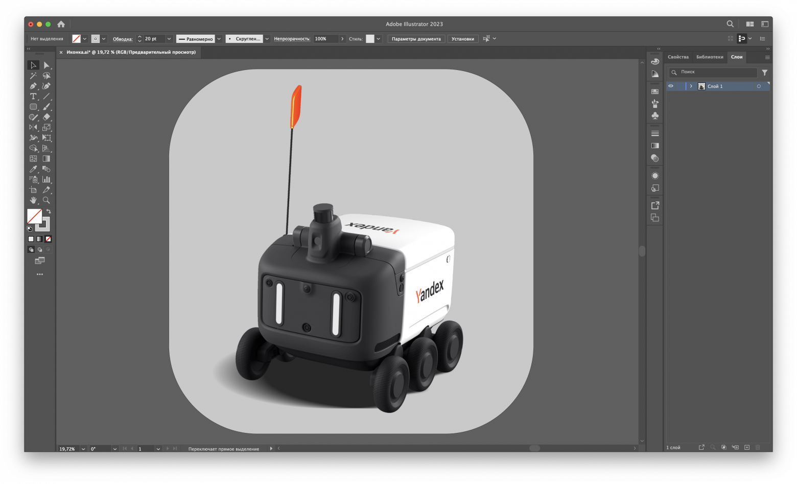
Mobile application icon
We assemble the application in Xcode, install it on a mobile device (in my case it’s an iPhone 12 Pro Max) and run it to test its performance. As a result, the mobile application received the following appearance:
Operation and appearance of the mobile application
Soldering, flux, two wheels
Then you can move on to soldering the elements, preparing the rover body and further installing the entire filling. To begin with, I decided to deal with the most important nuance - the wheels and the location of the motors inside the robot. I disassembled the original gear box to make sure both wheels were on the same metal rod. Having convinced myself of this, I removed both wheels with quite a lot of effort and attached them to the motors, having previously prepared the mounting points with an electric engraver (otherwise the motors would not have fit there).
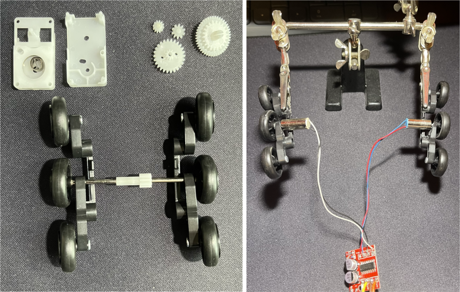
Rover wheels before and after connecting the motors
Next, I used the same engraver to cut off the unnecessary fasteners for the inertial mechanism box in order to get more space for the placement of boards and motors. I decided to put the battery with the charging board and the microcontroller in the “head” of the robot, and on the bottom under the container - the driver and the motors themselves.
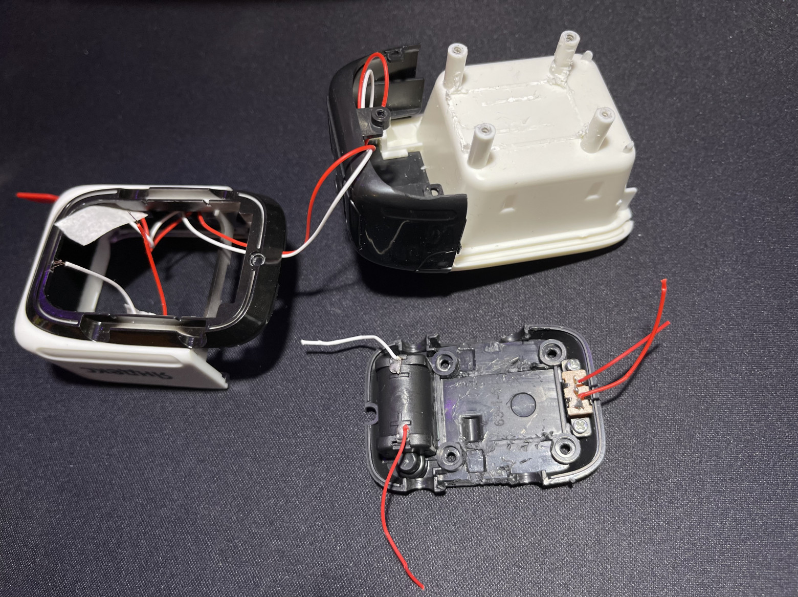
Disassembled rover with cut fastenings
To be able to charge the battery without disassembling the entire robot (because that's sadism), I sawed off the battery pack. At this point I will position the battery charging board so that the USB Type-C port faces the cover of the former battery pack. In this case, to charge the rover you only need to remove this cover and connect the cable to the charging board. I also cut out places for the motors, because there wasn’t enough space, and I didn’t want anything to interfere with their operation.
Modified rover underbody
After all the preparatory steps at the case level, I soldered the electronic components together in accordance with the connection diagram above. Please excuse me for the lousy duct tape, I didn’t do it on purpose. And if this is important for someone, I later washed off the excess flux from the microcontroller, so please don’t hit me.
Soldering rover electronic components
In the end, not without problems, but I was able to place all the components inside the rover. The device is charged from the bottom of the case. This reminds me of connecting a Magic Mouse, but I did it for lack of other options, and not because I don’t like people. The charging board could have been positioned differently, but I didn't want to spoil the appearance of the rover (the bottom doesn't count because it's not visible).
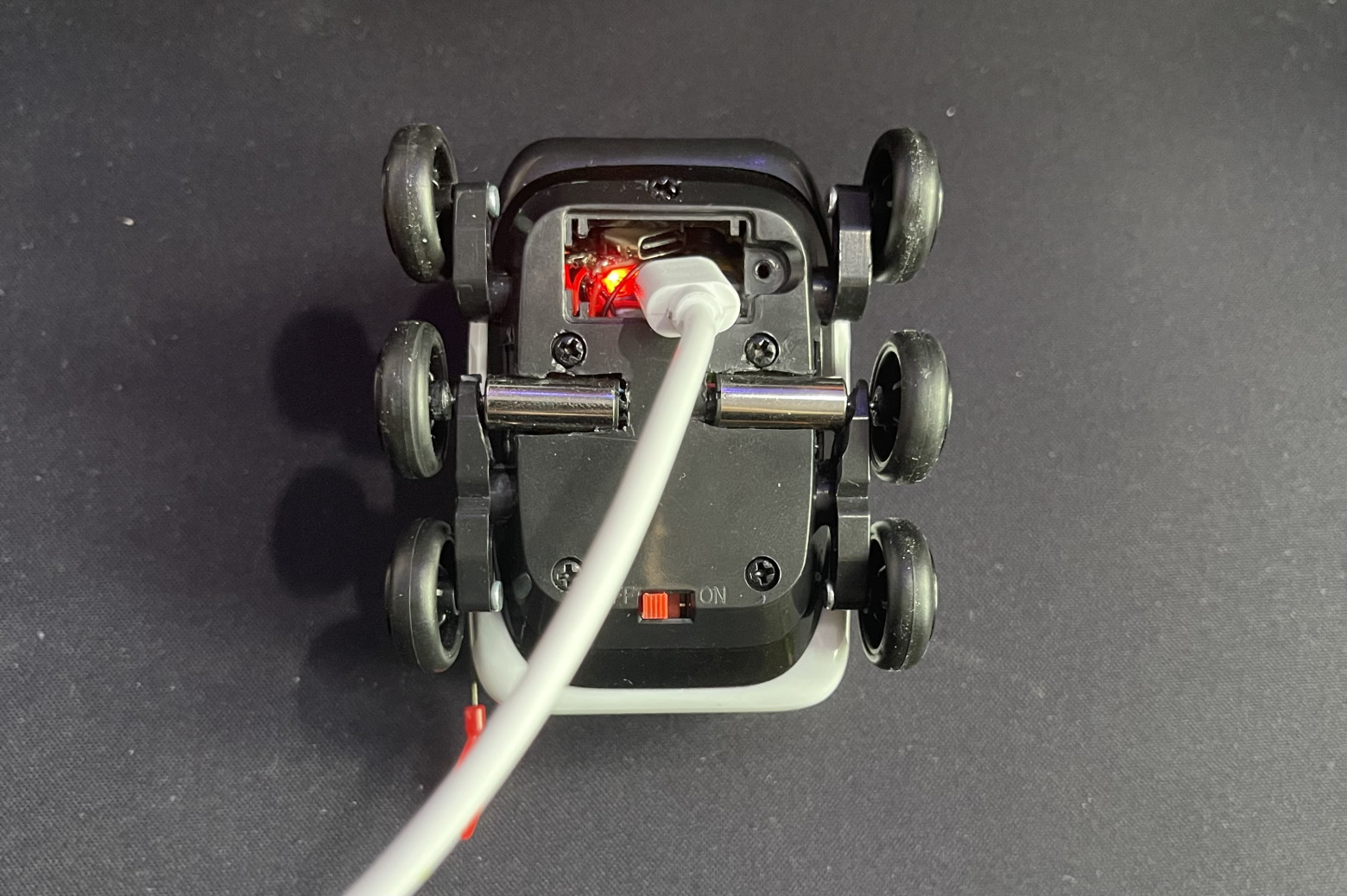
The process of charging the rover from the network
Let's go!
With this I have completed the modification of the toy. At first, I had thoughts of adding something else to the rover, for example a laser rangefinder, to try to recreate the logic of a real robot courier, but I abandoned this idea because there was no room left to place additional boards in it. I don’t want to saw the inside of the container for this purpose, because then the very essence of such a robot (even if it’s a toy one) is lost.
To demonstrate how to control the rover, I recorded a short video:
Bo Many thanks to everyone who read this article!
I will be incredibly grateful if you share your opinion about it in the comments. If you liked it, you can read my other articles, which are here . I promise you won't have a boring time.
UPD: Six months have passed since the publication of this article. Absolutely different people began actively writing to me asking me to modify a toy rover to order for them. I have already completed a series of orders with pleasure and continue to do so to this day. If you would like to purchase the same controlled delivery robot, write to me in a telegram ( https://t.me/MaxiEnergy ), and he will go to you)
Discussion
Comments
Comments are available only to confirmed email subscribers. No separate registration or password is required: a magic link opens a comment session.
Join the discussion
Enter the same email that you already used for your site subscription. We will send you a magic link to open comments on this device.
There are no approved comments here yet.